
17
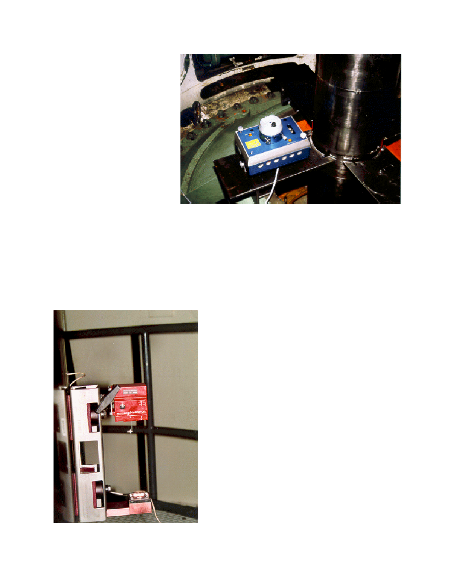
Photograph 4.--Hamar laser system.
Photograph 5.--Ludeca permaplumb system.
4.3 Permaplumb Laser
Alignment System
The Permaplumb system uses a
semiconductor laser, a
photoelectric semiconductor
position detector, and a mirror to
measure shaft plumb. The laser
and the position detector are
enclosed in a single monitor.
The mirror is calibrated and
balanced so that it is always
horizontal. The monitor and
mirror are mounted on the shaft
with a single mounting bracket
with two magnetic bases
(photo 5).
When the bracket is mounted to the shaft, the laser beam is directed down to the mirror and
reflected back to the position detector. The detector determines the relative position of the
reflected beam. The system takes samples of the X and Y coordinates of the beam position,
averages these samples, and transmits the average to a laptop computer. The computer has a
buffer that stores the last 120 readings. A smoothing function in the software of the computer is
applied to these readings to compensate for vibration.
Once the averaged or smoothed reading has stabilized,
it can be stored.
Once the averaged or smoothed reading has stabilized,
it can be stored.
The mirror's surface is always level and acts as the
reference for plumb for the system. If the laser beam
was perfectly parallel to the shaft center line, shaft
plumb could be determined from the averaged X and
Y coordinates on the computer screen. Since it would
be very time consuming, if not impossible, to make
the beam perfectly parallel to the shaft, the shaft must
be rotated and readings 180 degrees apart averaged.
This average provides the out of plumb of the center
of runout and not the actual position of the shaft. As
mentioned earlier, the goal of the alignment procedure
is to plumb the center of runout to make the thrust
bearing shoes level, so in most cases this is not a
problem. To determine the static runout diameter,
dial indicators can be set up at the thrust bearing and
turbine bearing elevations. From this information, the
shaft position and plumb can be determined.